So before I delve into the topic at hand, it’s been a while since I’ve really put any content up. The reasons are many along with the excuses, but hey it was just a new year a few months back right? Let’s try round two! 😀
One of my last posts was about some upcoming hardware that cost a pretty penny and I was really looking forward to getting my on them. Well, I’ve had my BCU’s since the end of October and I acquired two CVP’s since then. I also have a couple of Acorn 215+s. Things haven’t gone exactly to plan for us early adopters for a variety of reasons,though I’m guilty of throwing a wrench or two in the mix as well! The topic of this post is going to be my adventure with a special metal alloy called Indium and more importantly the install of the Dimastech Water Blocks for the BCU1525 FPGA. While the pictures I took will obviously have a few different steps than what you would do normally with some form of thermal paste, the overall disassembly and installation of the water blocks will be identical.
I didn’t necessarily think I was going to do a full article on this so my picture taking was limited, or rather, I jumped the gun on disassembly in my cointainer ™ but was forced to move to the house due to needing a stable temperature for reassembly. (Ambient in the cointainer ™ at the time was around 8C and I let all components come to room temperature before proceeding.) So what I’m really trying to say is I didn’t take all the pictures I should have, so I might have to steal some pics floating on the Internet for examples at times. Should be obvious when done so and credit for image will be given.
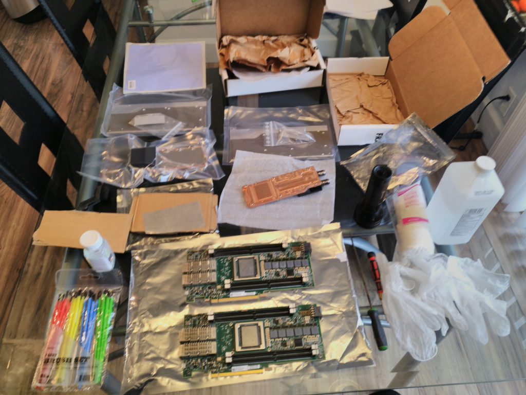
I’ll go over some of the supplies and tools I needed in order to accomplish this task, ones with an asterisk are specific to an Indium install. The one with a hash will be specific for a thermal paste install since duh, it’s thermal paste.
- Small Phillips Screw Driver
- Soft Nylon Brush
- E-Xacto Knife or Similar
- Small Paint Brushes *
- Conformal Coating – UV Reflective *
- Gloves * – unless you are anal about some paste on your fingers…
- UV Black Light *
- 50/50 Alcohol
- Cotton Swabs
- Lens Cleaning Cloth
- Thermal Paste of Choice # (I used Arctic MX-5)
- 150×150 1mm Thermal Pad
- 200×200 1.5mm Thermal Pad
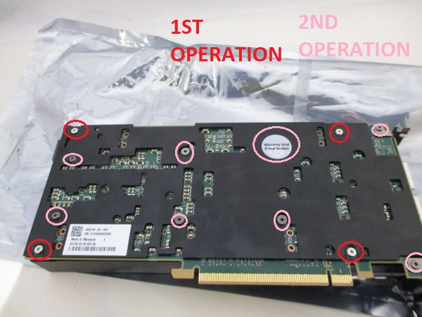
So to start breaking down the BCU1525 with the stock heatsink and shroud, you need to first remove the FOUR screws that hold the shroud in place. Refer to the image below for locations. These bolts are long and once you’ve removed them the shroud will come off. You are now left with another SIX spring loaded bolts to remove and TWO for the bracket . With all of these bolts removed and having voided the warranty seal, you can now remove the rear plate and set it aside. Now it’s time to separate the stock heat sink from the BCU1525. I found that the easiest way to accomplish this was to grasp the BCU1525 on the bracket side and then slowly pull the front plate away from the FPGA board. Eventually the grasp the OEM thermal interface material on the heatsink has will give and the heatsink should pop into your hand that should already be holding it from that side so it doesn’t go flying.
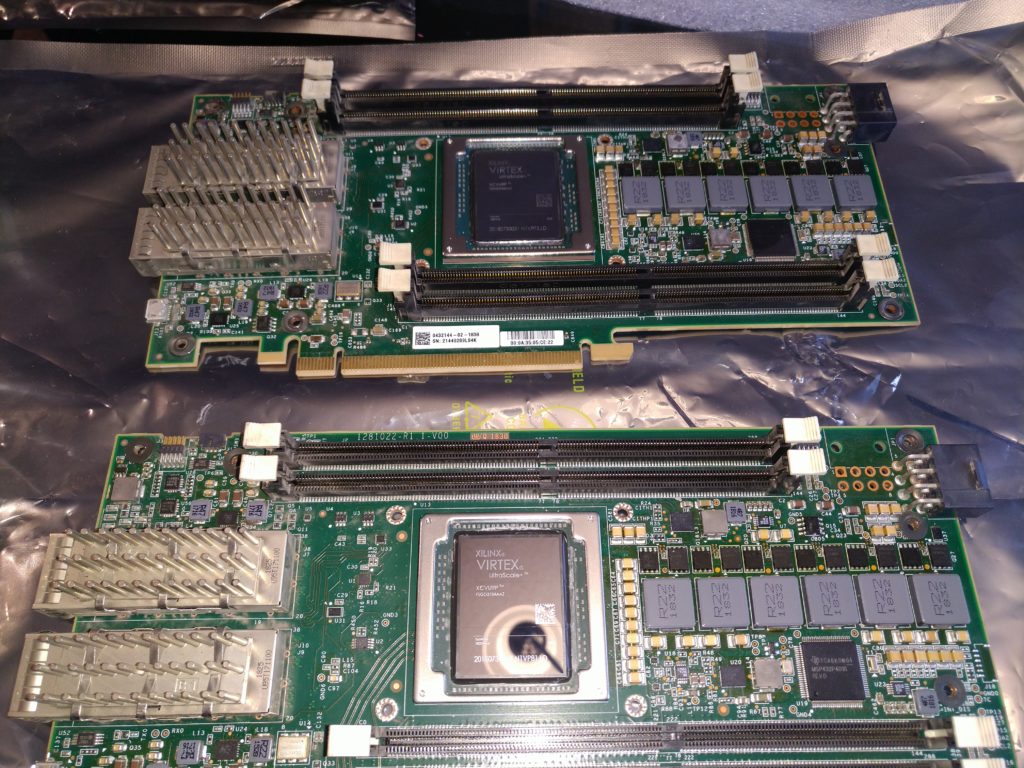
At this point you have pretty much separated the BCU1525 down to it’s major components and you should be able to set everything aside except for the FPGA board itself. The die of the FPGA is going to need to be cleaned before you can mount your expertly machined Dimastech water block. Let me take a sec to say how sexy and functional the Dimastech block is. I’m a car guy so I know all about function and form and the Dimastech block has both. Having more than a decade of automotive performance and seeing lots of custom CNC machining, I was thoroughly impressed by the quality of work in the product that I received. So back to cleaning dies. I found that it was best to use the screw driver (or a pick) to lightly scrape the factory paste from the chip’s joint to the board. If you don’t do this before you break out the alcohol, you end up with the paste being harder to clean up. By lightly scraping the residue away, you make the rest of the job of cleaning the die much easier. Once I’ve gotten the majority of the old material removed, I break out some cotton swabs and soak them in some alcohol. I proceed to clean the chip to the best I can, knowing that using a cotton swab is not the final step. Once the alcohol has had a chance to evaporate, I break out a lens cleaning cloth and give the die surface a final buff. When it glistens like a sparkly mirror, you know your done.

The next steps are not necessary for a non Indium install, but if you are crazy like me, the next steps would be to break out the conformal coating and the small paint brushes. This requires some delicate painting skills. Your goal is to coat the small tiny parts adjacent to the die to prevent any Indium from ever shorting anything out. (We wouldn’t want to explode $3,650 FPGA cards now would we?) My momma would have my ass since I used her money and she might even kick me out of her basement! (Joke, I don’t live in the basement! XD)

You can see my fine brush work in these very nicely illuminated pictures. There really isn’t very much to this step. Two thick coats should do it. The UV light really helps to see where you might have accidentally gotten the conformal coating. You really don’t want ANYTHING on the die. That is big no no no no. Got it?
So a buddy sent me a sample of some Indium to do some testing with. I have been so overloaded with real life that I haven’t gotten to do any testing as I thought I would on a bunch of CPUs. But, now that I finally have all my cards together in one place and was moving my BCU1525’s from air to water, now was the time to dip my toes and play with the big boys. Indium is supposed to have a low melting point and be extremely conductive when it comes to heat. Rumor mill has it that you really can’t beat this for a variety of applications. So since I have high end FPGA’s, why not try out some high end TIM? The Indium came in flattened sheet style. In order to cut the Indium I had to have a pattern first. So what did I do? I used a piece of thin cardboard to make a template. I cut it until it was the shape and size of the FPGA’s die. Now I used this template to cut out the Indium with the X-Acto knife. I was told you can also use scissors. But you know what I did before I did that? I put on my gloves. Yes lady (you can’t delete this) and gentlemen, Indium is a toxic substance. You really don’t want to be messing around with it irresponsibly. Look I’m a mechanic and I deal with lots of nasty things. I washed my hands like SIX times and I went through 3 pairs of gloves. I tried to minimize my handling of the Indium and I kept the equipment I used on it separate and also washed it when done.

So now I’ve got a piece of cut Indium (which I didn’t take any pictures of doh!) so let’s finish prepping for the Dimastech water block install. This needs to be done no matter what TIM you are going to use so pay attention. The FPGA die gets another once over with that cleaning cloth. I took the nylon brush and cleaned up the FPGA board. (My BCU1525’s were installed in an Antminer case with forced air so had some dirt) I take another cotton swab with alcohol and I cleaned up any oil residue from the old thermal pads on any and all components. Then I let it air dry as I began the tedious task of prepping the backing plate and water block with thermal pads. I have done this for two different cards and I want to echo Lokar’s recommendation about pad thickness. I ordered my first thermal pad a while ago and somehow only ordered one 200x200x1.5mm sheet instead of two. (I haz 2 BCU1525) So the first day I was only able to get one FPGA and block assembled and I used two layers of 1.5mm pads. This was a tight fit. This was also done on the Indium setup and I’m not sure if that has affected performance (I’ll get to that later). Since I had to order more, I looked on Discord and saw Lokar’s recommendation for one layer of 1.5mm and one of 1mm. So I ordered a 150x150x1mm sheet along with another 200x200x1.5mm sheet.
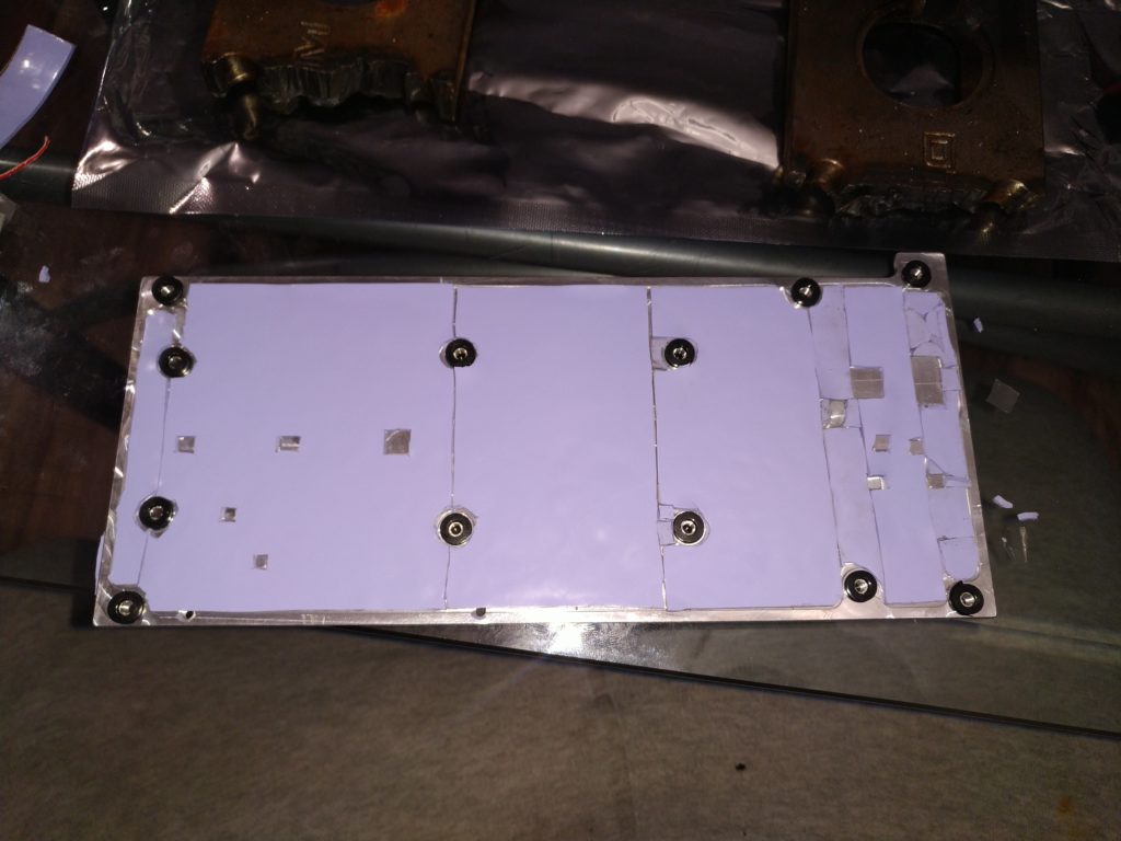
The 150x150x1mm sheet is used first. It’s JUST enough to do the backing. I’ve learned a trick for cutting out the holes but of course I didn’t figure it out until I was almost done with my second BCU (I have 2 remember? XD) If you press down very hard on the raised bumps you will leave their outline indented in the pad. Now cut out with a sharp X-Acto blade. Using this method you should end up with pretty accurate cuts. Try to cut it where you make as few cuts as possible. The fewer pieces you can make it, the better you are. Once you’ve installed the first layer, now drop the 1.5mm on it. The second layer only requires you to cut out the mounting holes. This layer should go on fast. Finish up, set it aside, and now it’s time for the water block itself.
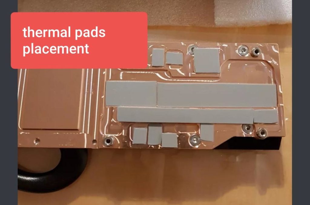
Refer to this image for placement of provided thermal pads on the water block. I pretty much did that but I used up more thermal pad material and covered more area. But that really is the gist of it. I only used provided thermal pad in this area.
So, if you are reading this and are going to be using some type of thermal paste, now would be the time to use it. I shouldn’t have to explain how to prep this should I? We are all vets here right? You can use something other than an Antminer da? 😀 Spread that paste like we want our ladies to spread their legs… (This is an all male audience right?) ha
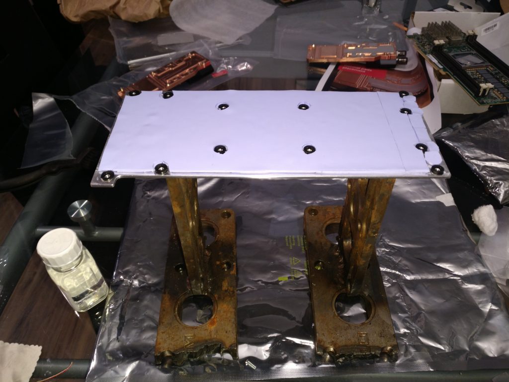
Ok now comes the moment of truth. Let’s assemble the parts so we can go party! The first step is to secure the water block to the card, the only problem is that the screws that do this (See those SIX recessed screws?) have to go through the backing plate first. This really isn’t a problem when you are using any kind of thermal paste, but when you use Indium, this creates a small challenge. The Indium doesn’t “stick” to the FPGA’s die like the paste does. Instead it’s like a sheet of paper. Any movement could seriously misalign a “precision” cut part. My solution for this was to use some stands I made in my former life to hold the backplate about 8″ off the table. I set the backplate on the stands, then I aligned the FPGA board with the holes in the backplate and set it on the backplate. Now came the fun part. With the Indium aligned on the die, I gently lowered the water block into place being mindful of the Indium location the entire time. I then had to hold the block in place with one hand while I grabbed the screwdriver and started threading in screws.


Like I previously mentioned, the first backplate I did had a total of 3mm of thermal pad on it. This created a tight fit and I had to firmly press down on the water block to be able to get the threads of the screws to engage. I highly recommend using 2.5mm total of thermal pad thickness. This was much easier to install. So once you get a few threads on a screw you go to the next and get all six in loosely. Now I started doing a turn or two on each screw and moving to an opposing screw, criss crossing and slowly tightening them up. My key focus was the four screws surrounding the FPGA die and the two outer ones were always done after those surrounding four. Eventually you get to a point where you just can’t tighten anymore without stripping the screw. Maybe you want to stop just ahead of that if you don’t know your own strength!
At this point it’s time to install the rest of the hex head socket cap screws to secure the backing plate to the board. You should have SIX screws left, FOUR shorter ones and TWO longer ones. The longer ones go with the frame bracket and the shorter ones go in the other holes. BE MINDFUL that these are installed FPGA side into the backing plate. DO NOT INSTALL FROM BACKING PLATE INTO FPGA. THAT IS INCORRECT.

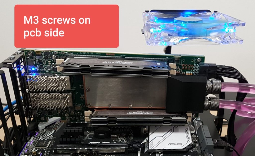
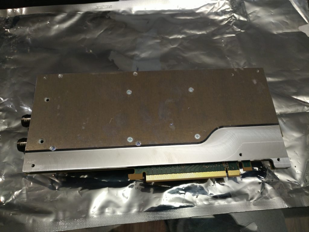
Now look over your newly Dimastech equipped BCU1525 and pick it up. Marvel at it’s heft. The BCU1525 almost feels indestructible now. Install your fittings of choice or use their distribution blocks. Just be mindful that the two unit version is meant for in chassis and will not work with risers. (There is a special version that will.) Install it into your chosen chassis and finish your plumbing and possible electrical work and get this bad boy fired up. It’s almost go time!

Well, if elected to use a thermal paste, it really is go time. I saw my chip temps reduce from 65C-85C depending on ambient on air down to 30C-43C with the same ambient range. I haven’t had too much of a chance to do any real tweaking, I’m just happy all four cards are finally up and running again.
Now if you decided to do Indium, well you still have a few steps to go. From what I’ve read and have been told, Indium requires a “break in” to steal another term from my former life. This break in is one where you rapidly get the chip up to 85 or 90C and then slowly bring it’s temperature back down to ambient. This is supposed to help “seat” the block onto the die. I did this but I haven’t seen the gains I was supposed to with Indium. My FPGA that has thermal paste is currently wiping the floor with the Indium based card. There is an almost 15C delta between the two.
Based on all I know, this leads me to believe that something is not right with my installation and I believe it’s due to the excess thermal pad not allowing me to tighten the block down properly. I’m going to have to pull this card back out and tear it down to inspect and see if I can’t come up with anything else. I already have some additional 1mm pad on order so I can also try with that.
All in all I’m extremely pleased with my Dimastech water block setup. I feel it was worth every penny. I’m a little disappointed about the distribution block I got not working, there was a little miscommunication that went on, but overall I really can’t complain. This product is exceptional in quality and performance and if I had more BCU1525’s, I’d have more of these water blocks. 🙂
thanks so much for this great article! All of your articles have been very helpful in my crypto mining endeavors. I am still having a lot of problems with my BCU1525 and my DL580 G7 +E7 cpus. I recently got some R910 servers I am hoping will be easier to diagnose since they aren’t subject to HP’s outrageous lockdown on drivers/firmware for their enterprise server hardware… Hope you will put something more out soon. I am interested to know the status of your operation
Hey there! You can get recent firmwares for your HP Proliant G7’s due to the Intel vulnerability. They are dated like February of 2018. If you need them, just write back and I’ll forward them to your email!